
The other articles, in this section on E30 motor control, were written around 2008/9 before present technology products were widely available. As a result a more up-to-date explanation of current usage techniques is given here.
When the E30 rules were formulated suitable timers were mostly clockwork with switching operated mechanically. When eventually electronic timers of a usable size, together with retrieval beacons, RDTs and micro servos became available, they all needed a power source. As the model’s motor battery was not capable of supplying all these accessories as well, it seemed logical to use an additional battery to power them.
This second battery must not be used to provide an extra source of power for the model’s flight motor. If this were so then such would clearly be in contravention of the battery size specification. When employing this method of timer operation care has to taken to ensure that no power from the timer battery is available to the model’s flight motor. The prevention of this extra power availability, and thus compliance with the rules, is the flier’s responsibility.
Terminology
No reference is made in the rules to the terminology used in this explanation so the general meaning of these terms should be helpful to those not familiar with them.
Power Train usually refers to the motor together with any drive used for its functioning and the battery (flight pack) powering it.
Drive refers to the control device for motor, either simple on/off switching or with speed control, and, for brushless motors, electronic commutation. This brushless motor type is usually referred to as an ESC.
Systems refers to items such as timers, DT mechanisms, servos and retrieval beacons.
Architecture refers to the layout and interconnection of the power train components and systems components.
Current and Previous usage
The motor timer does not form part of the power train. It cannot and does not provide power. It does provide a “signal” to the Power train instructing it how to operate; it provides information not power. Confusion arises from the operation of different types of drive.
Older types of drive for brushed motors are just simple on/off switches – no speed control – but contain a motor timer on the same board. Though compact and apparently convenient these are an older technology and require a second timer for the model’s DT.
Drives for both brushed and brushless motors, having an ESC, generally have no motor timer. With these it is usual to combine the motor timer with DT timer. This is the more modern technology and now more convenient as only one timer is required.
Confusion arises from the fact that brushless motor drives with ESCs can provide power “to” the timer – this is the usual arrangement for larger classes of electric model. However, timers in any form do not provide power.
A second battery powering the systems, if connected correctly, cannot supply power to the motor.
A simple check for compliance is the removal of the motor flight battery, with the timer/systems battery remaining connected and switched on; then operating the start switch should produce no response whatever from the motor.
The following diagrams show how to connect the various parts together.
Architecture Layouts
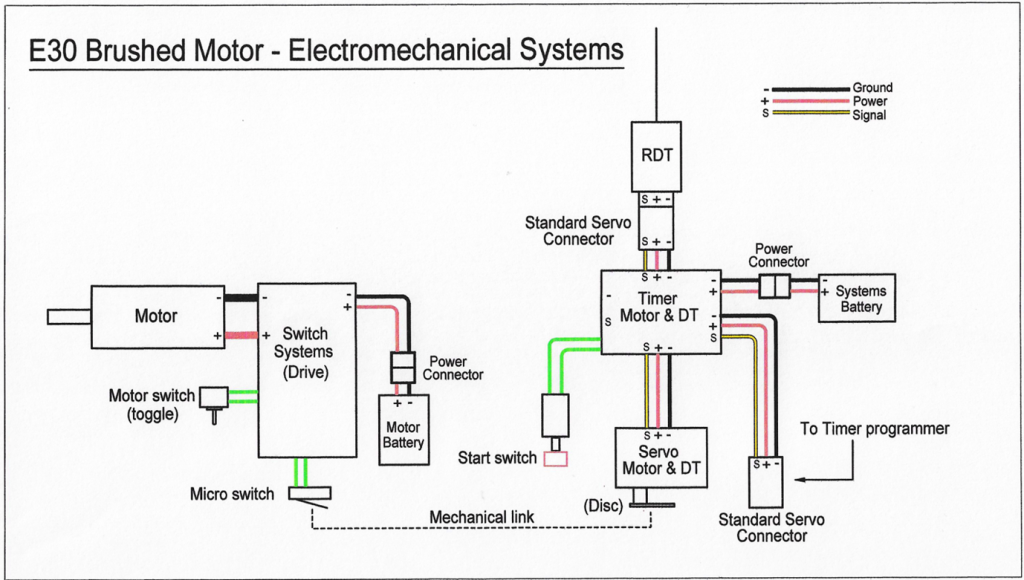
This first diagram is very much for reference. Few will want to take this route as it involves extra mechanical complication (more to go wrong). In particular it is possible to start the motor and launch the model ‘without’ the timer and systems running, resulting in a fly-away.
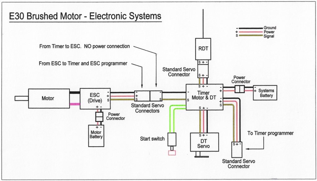
The next diagram shows a layout for a brushed motor. Some will want to use them for a variety of reasons though this type of motor has a lower efficiency than the brushless one. The ESC is a type specifically made for brushed motors – a brushless ESC will ‘not’ work. This ESC type is still available but getting harder to find. It is most important that there is no power connection between the ESC and the Timer and Systems otherwise there will be extra power provided to the motor making it illegal.
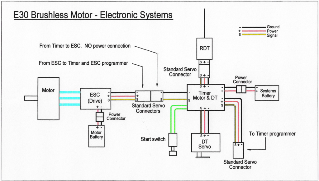
The last diagram shows the brushless motor layout. This gives the best efficiency, particularly important for the 60 second motor run specified by the rules. Some may wonder why, with both this layout and the previous brushed motor layout, there is still a power connection from the ESC to its own connector. This is solely to provide power to a programming card for the ESC. Most current ESCs require programming for set up and need power for this operation. When the card is in use the timer and systems are disconnected and the ESC’s connector plugged into the card. When the card is removed and the timer and systems reconnected there is now no power connection from the systems battery.
This is important. To repeat: check for compliance by unplugging the motor battery, but with the timer/systems battery still connected and switched on; then operate the start switch. There should be no response whatever from the motor.
Note that no retrieval beacons are shown on the diagrams. These, whether radio or GPS type are usually self contained and have own internal power sources so do not form part of the models systems.
(February 2023)